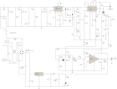
Input signals from the power line are coupled through C23 and R19 to the input filter network. C23 must be rated at 600 volts. Switch S2 is used as an attenuator. components C2 through C7, L1 through L3, R1, and R20 form a triple-tuned bandpass filter having a bandpass from 220-340 kHz. Signals from the filter are fed to an MC1350P gain block IC, which is used as a tuned RF amplifier.
IC2, the LM565 PLL, is used as an FM demodulator. Pins 8 and 9 are connected to an internal VCO and components R9, R10 and C15 set the VCO's free running frequency. The VCO signal and the input signal from pin 2 are compared in the phase detector. The output from the phase detector is internally amplified, and then appears at pin 7. The output at pin 7 is replica of the original modulation on the FM input signal to the receiver; the output at pin 7 is therefore the recovered audio. C17 and R14 couple audio to the base of Q2, which, in conjunction with R15, R16, R17, and C18, form an audio amplifier that brings the recovered audio up to around 1V peak-to-peak. The signal is then fed into an LM386N audio amplifier, which can deliver up to 1/2 W of audio, coupled via C20, to any standard 8 ohm external speaker.
 Click para ampliar


0 comments:
Publicar un comentario