Suitable for monitoring an amateur band or a segment of the radio spectrum, this simple adapter uses an NE602 mixer-oscillator chip to produces a 455-kHz IF signal, which U2 amplifies, then feeds to detector D2 and the Y axis of an oscilloscope. VT is used to drive the horizontal axis input of a scope. L2 and L3 are coils suitable for the frequency range in use. For this circuit, coils are shown for the 10- to 15-MHz range. L2 and L3 are wound on Amidon Associates, T-37 or T-50 toroidal cores, and L1 is a commercial or homemade variable inductor, etc.
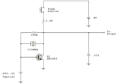
Scope Calibrator
The calibrator operates on exactly 100 kHz providing a reference for calibrating the variable time base oscillator of general purpose scopes. For example, if the scope is set so that one cycle of the signal fills exactly 10 graticule divisions then each division represents 1 MHz, or 1 microsecond. If the scope is adjusted for 10 cycles on 10 graticule divisions. (1 cycle per division) then each division represents 100 kHz or 10 microseconds.
Oscilloscope Counter Preamp
The circuit will provide a 20 0.1 dB voltage gain from 500 kHz to 50 MHz. The low-frequency response of the amplifier can be extended by increasing the value of the 0.05-mF capacitor connected in series with the input terminal. This circuit will yield an input-noise level of approximately 10 V over a 15.7-Mhz bandwidth. The gain can be calibrated by adjusting the potentiometer connected between pins 4 and 11. The 1-KW potentiometer can be adjusted for an exact voltage gain of 10. This preserves the scale factor of the instrument.
Oscilloscope Calibrator
The calibrator can be used to check the accuracy of a time-base generator, as well as to calibrate the input level of amplifiers. The calibrator consists of an NE555 connected in the astable mode. The oscillator is set to exactly 1 kHz by adjusting potentiometer P1 while the output at pin 3 is being monitored against a known frequency standard or frequency counter. The output level, likewise, is monitored from potentiometer P2's center arm to ground with a standard instrument. P2 is adjusted for 1 V pk-pk at the calibrator output terminal. During operation, the calibrator output terminal will produce a 1-kHz, square-wave signal at 1 V pk-pk with about 50% duty cycle. For long-term oscillator frequency stability, C1 should be a low- leakage mylar capacitor.
Four Trace Oscilloscope Adapter
This simple adapter uses an oscillator (567) to drive a counter (U2) and switch (U3) that selects the output of one of the four scope preamps (Q1/Q2 through Q7/Q8) and feeds it to buffer Q9 and output jack J1. J2 provides synch to the scope. R20 through R23 are posting controls for channels A through D (J3 through J6). S1A-B through S4A-B are switched attenuators, one for each channel. Switching rate is about 125 kHz. This circuit is useful for adding four-trace operation to inexpensive oscilloscopes. Signal levels of 0 to 20 V can be handled.
FET Dual Trace Scope Switch
The switcher output goes to the single vertical input of the scope, and a sync line from one of the inputs is taken to the scope's external-sync input. Frequency response of the input amplifiers is 300 kHz over the range of the gain controls. With the gain controls wide open so no attenuation of the signal takes place, the frequency response is up to 1 MHz.


